Description
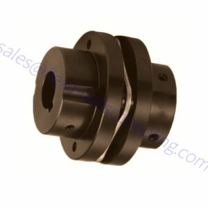
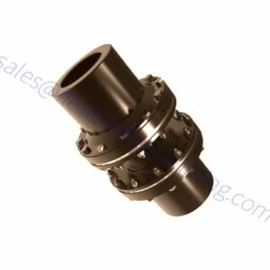
The difference between a single disc coupling and a double disc coupling is that the single disc coupling doesn’t accommodate parallel misalignment and will absorb fewer misalignments than a double disc coupling. However, the double-disc coupling can absorb more misalignments, including a parallel misalignment due to its dual discs.
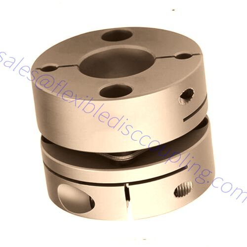
Single Disc Coupling Features
- High precision, designed for servo, stepping motor design.
- Seamless connection shaft and sleeve. Suitable for forwarding reverse.
- Low inertia, suitable for high speed.
- Shrapnel is made of stainless steel, which has excellent fatigue resistance.
- Clamp type.
Model meaning:
A1C Series
A1C-Outside diameter X Total length – d1 bore X d2 bore
Example: A1C-56X45-18X20
A: Aluminum
1: Single
C: Clamping Type
56: Outside diameter
45: Total length
18: d1 bore diameter
20: d2 bore diameter
Single Disc Coupling Size:
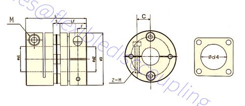
Single Disc Coupling Size
| Model | d1,d2, Bore | ΦD | L | Φd4 | LF | S | F | Wrench Torque
(N.M) |
| A1C-16×17 | 3,4,5,6, 6.35 | Φ16 | 17 | 6.5 | 7.8 | 3 | 2.65 | 1.5 |
| A1C-19×20 | 3,4,5,6, 6.35 ,7,8,9,10 | Φ19 | 20 | 8.5 | 9 | 2 | 2.2 | 1.5 |
| A1C-26×24 | 4,5,6, 6.35 ,7,8,9, 9.525 ,10,11,12, 12.7 ,14 | Φ26 | 24 | 10.5 | 10.65 | 2.7 | 3.4 | 1.5 |
| A1C-26×26 | 4,5,6, 6.35 ,7,8,9, 9.525 ,10,11,12, 12.7 ,14 | Φ26 | 26 | 10.5 | 11.65 | 2.7 | 3.9 | 2.5 |
| A1C-32×28.5 | 6, 6.35 ,7,8,9, 9.525 ,10,11,12, 12.7 ,14,15 | Φ32 | 28.5 | 14.5 | 12.25 | 3.9 | 3.9 | 2.5 |
| A1C-34×28.5 | 6, 6.35 ,7,8,9, 9.525 ,10,11,12, 12.7 ,14,15 | Φ34 | 28.5 | 14.5 | 12.25 | 3.9 | 3.85 | 2.5 |
| A1C-34×32.5 | 6, 6.35 ,7,8,9, 9.525 ,10,11,12, 12.7 ,14,15 | Φ34 | 32.5 | 14.5 | 14.25 | 3.9 | 4.85 | 3.5 |
| A1C-39×34.5 | 8,9, 9.525 ,10,11,12, 12.7 ,14,15,16,18,19 | Φ39 | 34.5 | 17 | 15.5 | 3.6 | 5.1 | 3.5 |
| A1C-44×34.5 | 8,9, 9.525 ,10,11,12, 12.7 ,14,15,16,18,19,20,22 | Φ44 | 34.5 | 20.5 | 15.5 | 3.6 | 5.1 | 3.5 |
| A1C-50×41.5 | 10,12,14,15,16,18,19,20,22,24,25 | Φ50 | 41.5 | 22.5 | 18 | 5.5 | 5.5 | 8 |
| A1C-56×45 | 12,14,15,16,18,19,20,22,24,25 | Φ56 | 45 | 26 | 19.75 | 5.8 | 6.4 | 8 |
| A1C-68×54 | 15,16,19,20,22,24,25,28,30,35 | Φ68 | 54 | 31 | 23.35 | 7 | 7.7 | 15 |
| A1C-82×69 | 22,24,,28,30,35,38,40 | Φ82 | 69 | 41 | 30 | 8.7 | 9.7 | 30 |
Specifications
| Model | Rated torque
(N·M)
|
Maximum
Torque (N·M) |
Allow Radial direction
(mm) |
Allow angle
( °)
|
Allow Axis
(mm) |
Maximum speed
Ramp |
Static torsional
Stiffness (N·M/rad) |
Moment of
Inertia (kg·M2) |
Weigh
g |
| A1C-16×17 | 1 | 2 | 0.1 | 1 | ±0.1 | 10000 | 280 | 2.2×10⁻⁷ | 8 |
| A1C-19×20 | 2 | 4 | 0.1 | 1 | ±0.1 | 10000 | 560 | 6.7×10⁻⁷ | 11 |
| A1C-26×24 | 3.5 | 7 | 0.1 | 1 | ±0.1 | 10000 | 1125 | 2.1×10⁻⁶ | 25 |
| A1C-26×26 | 3.5 | 7 | 0.1 | 1 | ±0.1 | 10000 | 1125 | 2.2×10⁻⁶ | 28 |
| A1C-32×28.5 | 8 | 16 | 0.1 | 1 | ±0.1 | 10000 | 2100 | 7.1×10⁻⁶ | 46 |
| A1C-34×28.5 | 8 | 16 | 0.1 | 1 | ±0.1 | 10000 | 2550 | 7.5×10⁻⁶ | 50 |
| A1C-34×32.5 | 8 | 16 | 0.1 | 1 | ±0.1 | 10000 | 2550 | 8.0×10⁻⁶ | 55 |
| A1C-39×34.5 | 15 | 30 | 0.1 | 1 | ±0.1 | 10000 | 3900 | 2.2×10⁻⁶ | 81 |
| A1C-44×34.5 | 18 | 36 | 0.1 | 1 | ±0.1 | 10000 | 4500 | 2.8×10⁻⁵ | 180 |
| A1C-50×41.5 | 20 | 40 | 0.1 | 1 | ±0.1 | 10000 | 5000 | 3.5×10⁻⁵ | 180 |
| A1C-56×45 | 30 | 60 | 0.1 | 1 | ±0.1 | 10000 | 12900 | 1.2×10⁻⁴ | 217 |
| A1C-68×54 | 60 | 120 | 0.1 | 1 | ±0.1 | 10000 | 25800 | 1.5×10⁻⁴ | 348 |
| A1C-82×69 | 100 | 200 | 0.1 | 1 | ±0.1 | 10000 | 38700 | 1.8×10⁻⁴ | 689 |