Product Description
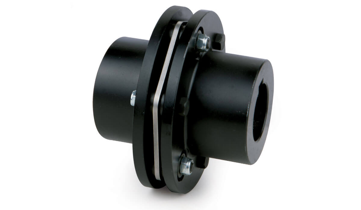
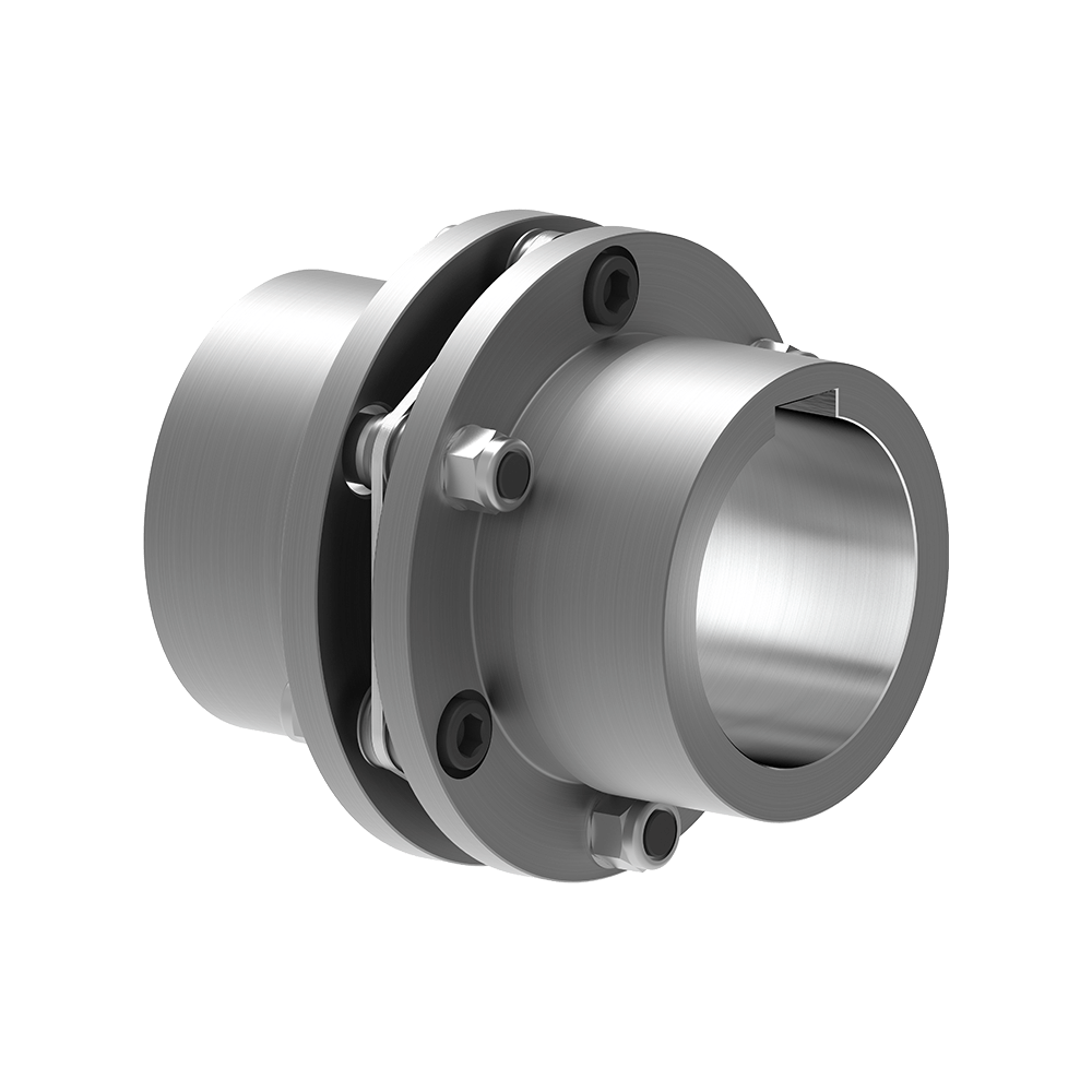
PGCLK Drum Gear Coupling with Brake Disc(Q/LZP02.02-2005)
♦Description
Drum gear type coupling belongs to rigid flexible coupling, gear type coupling is composed of inner gear ring and flange half coupling with outer gear with same number of teeth.Can improve the contact conditions of teeth, improve the ability to transfer torque, extend the service life.Radial, axial and angular axis deviation compensation ability, has a compact structure, small turning radius, large carrying capacity, high transmission efficiency, low noise and long maintenance cycle, especially suitable for the condition of low speed and heavy loading, such as metallurgy, mining, lifting transportation and other industries, can also be applied to petroleum, chemical industry, general machinery and other kinds of shaft transmission of machine.
♦Main Dimension and Parameter(Q/LZP02.02-2005)
| Type | Nominal Torque Tn/(N·m) |
Allowable Speed (n)/(r/min) |
Bore Diameter d1d2dz |
Bore Length (L) |
D0 | D | D1 | D2 | D3 | L0 | T | C1 | C2 | e | Grease dosage(v) mL |
Mess (m) kg |
Rotary inertia(l) L/(kg·m2) |
||
| Driven | Drive | Y | J1Z1 | ||||||||||||||||
| PGCLK1 | 630 | 4000 | 20 | 24 | 52 | 38 | 315 | 125 | 95 | 60 | 80 | 90 | 30 | 25 | 39 | 30 | 55 | 7.0 | 0.01 |
| PGCLK2 | 1120 | 4000 | 25 | 28 | 62 | 44 | 315 | 144 | 120 | 75 | 95 | 105 | 30 | 25.5 | 44 | 30 | 100 | 11.2 | 0.03 |
| PGCLK3 | 2240 | 3550 | 30 | 38 | 82 | 60 | 355 | 174 | 140 | 95 | 115 | 130 | 30 | 18 | 40 | 30 | 140 | 21.3 | 0.05 |
| PGCLK4 | 3550 | 2500 | 32 | 38 | 82 | 60 | 40 | 196 | 165 | 115 | 130 | 130 | 30 | 29 | 47 | 30 | 170 | 29.5 | 0.11 |
| PGCLK5 | 5000 | 2500 | 40 | 56 | 112 | 84 | 400 | 224 | 183 | 130 | 150 | 150 | 30 | 18 | 43 | 30 | 270 | 47.1 | 0.20 |
| PGCLK6 | 7100 | 2000 | 48 | 56 | 112 | 84 | 450 | 241 | 200 | 145 | 170 | 155 | 30 | 21 | 50 | 30 | 380 | 60.1 | 0.31 |
| PGCLK7 | 10000 | 1700 | 60 | 75 | 142 | 107 | 450 | 265 | 230 | 160 | 190 | 180 | 30 | 19 | 50 | 30 | 570 | 88.9 | 0.56 |
| PGCLK8 | 14000 | 1700 | 65 | 75 | 142 | 107 | 500 | 285 | 245 | 175 | 210 | 180 | 30 | 20 | 50 | 30 | 660 | 105.4 | 0.79 |
| PGCLK9 | 18000 | 1600 | 70 | 75 | 142 | 107 | 560 | 314 | 270 | 200 | 225 | 200 | 30 | 25 | 60 | 30 | 700 | 130.1 | 1.22 |
| PGCLK10 | 31500 | 1600 | 80 | 95 | 172 | 132 | 800 | 346 | 300 | 220 | 250 | 230 | 30 | 20 | 58 | 30 | 900 | 191.2 | 2.17 |
| PGCLK11 | 40000 | 1400 | 100 | 120 | 212 | 167 | 800 | 385 | 330 | 260 | 285 | 260 | 30 | 21 | 64 | 40 | 1200 | 268.2 | 3.88 |
| PGCLK12 | 56000 | 1400 | – | 120 | 212 | 167 | 900 | 442 | 380 | 290 | 325 | 280 | 30 | 21 | 72 | 40 | 2000 | 369.9 | 6.90 |
| PGCLK13 | 80000 | 1400 | 140 | 150 | 252 | 202 | 900 | 482 | 420 | 320 | 360 | 320 | 30 | 22 | 70 | 40 | 3000 | 522.6 | 11.91 |
| PGCLK14 | 112000 | 1200 | 160 | 180 | 302 | 242 | 900 | 520 | 465 | 360 | 410 | 360 | 30 | 23 | 85 | 40 | 4500 | 756.9 | 20.70 |
Note:
1. The mass and moment of inertia of the coupling are approximate values calculated according to the minimum shaft hole diameter and maximum shaft hole length in each type;
2. The maximum braking torque Tm of the coupling shall not exceed 2 times of the nominal torque Tn, that is, Tm≤ 2Tn;
3. e is the size required for sealing;
4. The combination of coupling shaft hole is Z1/J1, Y/Y, J1/J1, Y/J1.
♦Other Products List
| Transmission Machinery Parts Name |
Model |
| Universal Coupling | WS,WSD,WSP |
| Cardan Shaft | SWC,SWP,SWZ |
| Tooth Coupling | CL,CLZ,GCLD,GIICL, GICL,NGCL,GGCL,GCLK |
| Disc Coupling | JMI,JMIJ,JMII,JMIIJ |
| High Flexible Coupling | LM |
| Chain Coupling | GL |
| Jaw Coupling | LT |
| Grid Coupling | JS |
♦Our Company
HangZhou CHINAMFG Machinery Manufacturing Co., Ltd. is a high-tech enterprise specializing in the design and manufacture of various types of coupling. There are 86 employees in our company, including 2 senior engineers and no fewer than 20 mechanical design and manufacture, heat treatment, welding, and other professionals.
Advanced and reasonable process, complete detection means. Our company actively introduces foreign advanced technology and equipment, on the basis of the condition, we make full use of the advantage and do more research and innovation. Strict to high quality and operate strictly in accordance with the ISO9000 quality certification system standard mode.
Our company supplies different kinds of products. High quality and reasonable price. We stick to the principle of “quality first, service first, continuous improvement and innovation to meet the customers” for the management and “zero defect, zero complaints” as the quality objective.
♦Our Services
1. Design Services
Our design team has experience in Cardan shafts relating to product design and development. If you have any needs for your new product or wish to make further improvements, we are here to offer our support.
2. Product Services
Raw materials → Cutting → Forging →Rough machining →Shot blasting →Heat treatment →Testing →Fashioning →Cleaning→ Assembly→ Packing→ Shipping
3. Samples Procedure
We could develop the sample according to your requirement and amend the sample constantly to meet your need.
4. Research & Development
We usually research the new needs of the market and develop the new model when there is new cars in the market.
5. Quality Control
Every step should be a special test by Professional Staff according to the standard of ISO9001 and TS16949.
♦FAQ
Q 1: Are you a trading company or a manufacturer?
A: We are a professional manufacturer specializing in manufacturing various series of couplings.
Q 2: Can you do OEM?
Yes, we can. We can do OEM & ODM for all the customers with customized artworks in PDF or AI format.
Q 3: How long is your delivery time?
Generally, it is 20-30 days if the goods are not in stock. It is according to quantity.
Q 4: Do you provide samples? Is it free or extra?
Yes, we could offer the sample but not for free. Actually, we have a very good price principle, when you make the bulk order the cost of the sample will be deducted.
Q 5: How long is your warranty?
A: Our Warranty is 12 months under normal circumstances.
Q 6: What is the MOQ?
A: Usually our MOQ is 1 pcs.
Q 7: Do you have inspection procedures for coupling?
A: 100% self-inspection before packing.
Q 8: Can I have a visit to your factory before the order?
A: Sure, welcome to visit our factory.
Q 9: What’s your payment?
A: T/T.
♦Contact Us
Web: huadingcoupling
Add: No.11 HangZhou Road,Chengnan park,HangZhou City,ZheJiang Province,China
/* January 22, 2571 19:08:37 */!function(){function s(e,r){var a,o={};try{e&&e.split(“,”).forEach(function(e,t){e&&(a=e.match(/(.*?):(.*)$/))&&1
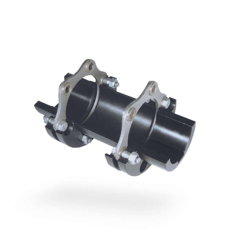
Materials Used in Manufacturing Disc Couplings
Disc couplings are typically constructed using a combination of high-quality materials that contribute to their durability, strength, and performance. Some commonly used materials include:
- Stainless Steel: Stainless steel is a popular choice due to its corrosion resistance and high strength-to-weight ratio. It ensures longevity and can withstand harsh environments.
- Aluminum: Aluminum is known for its lightweight properties and is often used in applications where weight reduction is essential while maintaining reasonable strength.
- Steel: Carbon or alloy steel is chosen for its robustness and ability to handle high torque loads and harsh operating conditions.
- Bronze or Brass: These materials can be used in specific applications where electrical conductivity is a concern, or when friction and wear properties are important.
The selection of materials depends on factors such as the coupling’s intended application, torque requirements, environmental conditions, and the desired balance between strength, weight, and resistance to wear and corrosion.
Recent Advancements in Disc Coupling Design
Disc coupling technology has seen continuous advancements to enhance performance, reliability, and adaptability to various applications. Some recent innovations in disc coupling design include:
- Material Enhancements: The development of new materials, such as advanced alloys and composite materials, has improved coupling durability, corrosion resistance, and overall lifespan.
- Flexible Disc Profiles: Innovative disc profiles are designed to optimize flexibility while maintaining torque transmission capabilities, allowing for better misalignment compensation and shock absorption.
- Modular Designs: Modular disc coupling systems offer flexibility in adapting to different torque and misalignment requirements, making them versatile for a wide range of applications.
- Enhanced Torsional Stiffness: Some designs focus on achieving higher torsional stiffness, ensuring accurate torque transmission and responsiveness even in demanding conditions.
- Smart Couplings: Integration of sensor technology enables real-time monitoring of coupling performance, allowing for predictive maintenance and reducing downtime.
These advancements are driven by the increasing demands of modern machinery and the need for higher efficiency, reduced maintenance, and improved overall system performance. Engineers and manufacturers are continually exploring new ways to optimize disc coupling design for a variety of industries and applications.
Considerations for Selecting a Disc Coupling for a Specific Application
Choosing the right disc coupling for a particular application involves considering several important factors to ensure optimal performance and reliability:
- Torque Requirements: Determine the maximum and continuous torque requirements of the application. Select a disc coupling that can handle the expected torque without exceeding its rated capacity.
- Misalignment: Evaluate the type and magnitude of misalignment expected in the system, including angular, parallel, and axial misalignment. Choose a disc coupling with the appropriate misalignment capability to accommodate these factors.
- Speed and RPM: Consider the operating speed and rotational speed of the connected shafts. High-speed applications may require disc couplings with balanced design to prevent vibration issues.
- Space Limitations: Evaluate the available space for installing the coupling. Disc couplings are compact and can be suitable for applications with limited space.
- Environmental Conditions: Assess the operating environment, including temperature, humidity, presence of corrosive agents, and exposure to dust or debris. Choose materials and coatings that can withstand the environmental conditions.
- Shaft Sizes: Ensure that the disc coupling’s hub bore sizes match the shaft sizes of the connected equipment.
- Alignment Maintenance: Consider the ease of installation and alignment maintenance. Some disc couplings feature spacer elements that simplify alignment and reduce downtime during maintenance.
- Backlash: Evaluate the backlash or play that the coupling introduces between the shafts. Backlash can affect the accuracy of position and torque transmission in precision applications.
- Dynamic Balancing: For high-speed applications, consider disc couplings that are dynamically balanced to prevent vibration issues that can arise from rotational imbalance.
- Resonance and Damping: Determine if the coupling design includes features to dampen vibrations and reduce the risk of resonance in the system.
- Service Life: Estimate the expected service life based on the application’s duty cycle and requirements. Choose a disc coupling with a suitable service life to avoid frequent replacements.
- Cost and Value: Compare the cost of the disc coupling with its features, performance benefits, and expected lifespan. Choose a coupling that provides the best value for your specific application.
By carefully considering these factors, you can select a disc coupling that meets the unique requirements of your machinery system and ensures reliable operation.


editor by CX 2024-03-04